Phase Modulation for Synthesizers

On nsigma’s request (from the “Extremely Fast sine…” thread)

The code is actually being used for phase modulation at this point, not frequency modulation. So maybe I should change the name to PMOp. While I was developing, I had some actual frequency modulation implementations as well but have “phased” them out.

public interface FMOp
{
	float get();
	float get(float modAmt);
	void setFrequency(float freq);
}

The initials PML derived from Phase Modulation Lookup. I previously had tried calculating the sine values, but couldn’t find an algorithm fast and accurate enough to compete with the lookup I’m using (1024 unit table with linear interpolation, posted on the thread cited below). I’d be most grateful to learn of a faster method (will be reading closely and trying out methods from here: http://www.java-gaming.org/topics/extremely-fast-sine-cosine/36469/msg/346129/view.html#msg346129)

[EDIT 7/30/15: renamed “index” to “cursor” in order to make the three implementations consistent.]

public class OpPML implements FMOp
{
	// "public" okay, for internal use only
	float cursor;
	float pitchIncr;
	final int tblSize = SineTable.getOperationalSize();
	
	public void setFrequency(float freq)
	{
		pitchIncr = (freq * tblSize)/ 44100;
	}
	
	// TODO: should not be used, should set to cause compile error
	@Override
	public float get()
	{
		return get(0);
	}
	
	@Override
	public float get(float modulationAmt)
	{
		cursor += pitchIncr;
		if (cursor >= tblSize ) cursor -= tblSize;
		
		float temp = cursor + modulationAmt;
	
		while (temp < 0) temp += tblSize;
		while (temp >= tblSize) temp -= tblSize;
		
		return SineTable.get(temp); 
	}
}

Variant with no modulator. Yes, lots of duplicate code. But minimizing processing in the .get() has the highest priority.

public class OpN implements FMOp
{
	// "public" okay, for internal use only
	float cursor;
	float pitchIncr;
	final int tblSize = SineTable.getOperationalSize();
	
	public OpN(){}
	
	public OpN(float freq)
	{
		this();
		this.setFrequency(freq);
	}
	
	public OpN(float freq, float startingPhase)
	{
		this();
		this.setFrequency(freq);
		cursor = startingPhase * tblSize;
	}
	
	public void setFrequency(float freq)
	{
		pitchIncr = (freq * tblSize) / 44100f;
	}
	
	@Override
	public float get()
	{
		cursor += pitchIncr;
		if (cursor >= tblSize) cursor -= tblSize;
		
		return SineTable.get(cursor); 
	}

	// TODO: should cause compile error, should not be used
	@Override
	public float get(float modulationAmt)
	{
		return 0;
	}
}

Variant that uses feedback instead of an external modulation source.

public class OpFB implements FMOp
{
	// "public" okay, for internal use only
	float cursor;
	float pitchIncr;
	final int tblSize = SineTable.getOperationalSize();
	private float feedback;
	
	final private float feedbackAmplitude;
	
	public OpFB(float feedbackAmplitude)
	{
		this.feedbackAmplitude = feedbackAmplitude;
	}
	
	public void setFrequency(float freq)
	{
		pitchIncr = (freq * tblSize) / 44100f;
	}
		
	@Override
	public float get()
	{
		// determine feedback amt
		cursor += pitchIncr;
		if (cursor >= tblSize) cursor -= tblSize;
		
		feedback = SineTable.get(cursor);
		
		feedback = cursor + feedback * feedbackAmplitude;
		while (feedback >= tblSize) feedback -= tblSize;
		
		return SineTable.get(feedback); 
	}
	
	// TODO: trigger compiler error, never should be used
	@Override
	public float get(float modulationAmt)
	{
		return 0;
	}
}

With these three, one can replicate all 32 “algorithms” employed by the Yamaha DX-7. Here is an example of the code I use for a simple modulator -> carrier pair:

				currentCEnv.tick(cEnvCursor, frequency);
				currentMEnv.tick(mEnvCursor, frequency);
				
				float noteVal = 
						vmCarrier.get(cEnvCursor.value)
						* cOp.get(
							vmModulator.get(mEnvCursor.value)
							* modDepth1 * mOp.get()
						);

cOp is an OpPML
mOp is an OpN
There are envelop/cursor pairs for the carrier and modulator.
There is also another layer of mapping that converts the linear values to something more exponential/logarithmic. I am calling these “volume maps” (amplitude maps would be better?). For modulators, I usually use a “reverse cosine” mapping (1 - cos, for 1/4 of a cycle), and for carriers an exponential mapping (x^6, x=0…1) works pretty well. I was not able to figure out what Yamaha/Stanford folks were using here. nsigma, maybe you understand this better and have a suggestion for this step? My head is a little far away from the theory at the moment. Maybe there is a decibel/logrithmic function-related that would be more ideal.

[EDIT: following added 7/30/15]
Examples of FM synthesis, previously posted on JGO, can be heard playing the jars listed at the following links:
http://www.java-gaming.org/user-generated-content/members/27722/tanpura141204.jar
http://www.java-gaming.org/user-generated-content/members/27722/hexarasoundtester141130.jar

The first has a simple square and sawtooth included (just 2 ops, 2:1 and 1:1), but with pretty active envelopes, so they sound relatively reasonable. (Mouse over the note “node” on the display dial, and select from the bottommost drop-down.) The two main patches (etanpura, cirrus) have 6 ops, with a lot more internal phasing built in, for a richer sound. Oh, and the tanpura-drone project also has a basic FM-type electric-piano keyboard implemented. The second jar has a nice pad and bell/gongs.

I’ve another half-dozen patches implemented now–will be showing off a little sequencer/motif player soon. I just want to first implement “hairpins” (crescendos/dims) as part of the “event system” before doing so. Might take a couple weeks to get to it.

Excellent resource:
From Dave Benson, from his book posted online on music maths, specifically on FM:
http://homepages.abdn.ac.uk/mth192/pages/html/music.pdf#section.8.8
This chapter has a good reference section at the end to check out! There is also “Appendix O: Online Articles”.

Thanks for posting this, and sorry it’s taken a couple of days to find enough time to read it properly.

I understand this far less! :wink: The new Praxis LIVE release (out in a couple of weeks) will have live audio coding capability. I’ve been trying to get my head around FM / PM synthesis to test it, but it’s really new to me. I think the algorithm I’m using is the same as yours, although I haven’t tried adding in envelopes yet, which I guess is fairly fundamental.
From an amplitude perspective, a power curve should approximate the dB response. This article might be worth a look - http://www.dr-lex.be/info-stuff/volumecontrols.html I was thinking of following the advice there of ^4

One thing I don’t get is why you’re using a cos curve on the modulation amplitude. Would you not use the same amplitude mapping there?

[Edited 7/30/15]
Thanks for the article link! Nice to see some confirmation and clarification. I am also interested in ideas for a good power curve for panning. For now, I’m just using two linears, in reverse directions, one for each channel, with the plan to work on a better version if/when I get into true 3D or another situation that demands power balancing throughout the panning range.

I went through a process of trial an error for the carrier and modulator power curves, testing by ear. The “VolumeMap” object I created can have its LUT (similar in implementation to what I posted on the ‘fastest sin’ thread) populated by any number of methods. This made it pretty easy to swap the various maps in and out for comparison purposes. The ones that I implemented and compared follow:

  • reverse cos : 1 - cos(x) where x [0…PI/2]

All of the rest, x goes from 0 to 1:

  • linear
  • 2^x - 1
  • (10^x - 1) / 9
  • (20^x -1) / 19
  • x^e
  • x^2
  • x^3
  • x^4
  • x^5
  • x^6
  • x^7
  • x^10

and a few miscellaneous experiments that didn’t work out at all.

I compared the results, by ear, with numbers plugged into the Yamaha DX7 or Native Instruments FM7. I don’t consider my choices “final” answers.

I recall x^4 (the article’s “overall best”) was pretty good, but I guess I am working with a larger dynamic range, hence using the higher exponent values. I remember being indecisive between x^5 and x^6 early on. Lately, I just start with the two I mentioned and try others only if I am have an audible goal in mind. For example some patches, x^7 seems to work better than x^6. The times x^7 works best are patches where the envelope levels are transitioned via “EXP” curves rather than linearly in the “parent” synth.

Thanks to this discussion, I just found another option to try: mapping derived from a Bessel function. Check out the following link, “Appendix B: Bessel Functions” from Dave Benson’s book on music related mathematics.

http://homepages.abdn.ac.uk/mth192/pages/html/music.pdf#appendix.B

At the very end of this appendix section is a table, with the caption:

[quote]The following table shows how index of modulation (z) varies as a func-
tion of operator output level (an integer in the range 0–99) on the Yamaha
six operator synthesizers DX7, DX7IID, DX7IIFD, DX7S, DX5, DX1, TX7,
TX816, TX216, TX802 and TF1
[/quote]
I don’t know much at all about Bessel functions, or even if this table arises from Bessel functions other than that it is in the “Bessel” appendix. In this table, I take it that 1.0 is one complete modulation cycle. To be more concrete: I have a sin LUT of 1024. An offset of 360 degrees would be once through the sine table, so a modulation index or amplitude of 1024 in my OpPML should correspond to the DX7S modulation index value of between 69 and 70. This rings true for the patches I’ve recreated. I’m going to have to confirm. I’m also going to have to experiment with using this table (with linear interpolation) for the modulation values that arise by applying the envelope to the modulation index. [EDIT8/2/15 Perhaps logic here is wrong. Since the MI is being multiplied against an output of range -1 to 1, a range of half the sine LUT is equal to a MI of 1? But even that is too high for the synth I have programmed. I’m getting an MI of 150 +/- 10 (with LUT of size 1024) as the closest, by ear, to DX7 MI of 69, or ‘1’ according to Benson’s chart. Hmmm.]

Envelopes should be pretty much the same as they are for subtractive synthesis or wave-table synthesis. Yes? No? I’m assuming you are using outputs that range from 0 to 1 and are multiplied in (but with a power curver). I assumed you have already implemented that sort of thing. I recall a JGO post with you and “AngryOctopus” (ShannonSmith), exchanging links to software synthesizers you had each made.

I think I have a pretty nifty envelope working (updates every frame), but am curious how you do it, and possible improvements.

It makes sense to me that the two power curves serve very different functions. The power functions used on carriers reflects an operation done to convert a linear scale for amplitudes to something that matches our “logarithmic” perception of loudness. The discussion in the volume controls article cited gets into particulars about picking an equation for expressing a range of a desired low to high db.

The function used for modulation amounts affects an operation that progressively changes harmonic content by propagating sidebands. The math used to determine sideband propagation uses Bessel functions. I don’t know if there is much of a correspondence between the Bessel functions and exponential or logarithmic curves, or not, nor how the changes in timbre relate to units of human perception.

I guessed “reverse cos” based on listening and trial and error as being workable, and got some good results. But probably the work done by Chowning at Stanford and confirmed by Yamaha, using the published function table, is solid, and should be emulated. (Their chart may even be a normal power function of some sort.)

That said, it would be nice to be able to generate the values via an equation rather than just copy them from an existing table.

Looking up Bessel functions, though, all I can say is yikes!


They make use of differential equations, and the results are spread out over the various sidebands. It doesn’t appear be a curve that itself is going to be used for a simple amplitude mapping, not with those “wavy parts”!

On this sine thing…you’re just walking sine at a constant rate?

In the FMOp’s (often called Operators) that remain implemented, yes, the sine progresses at a constant rate. The cursor value moves one equal fraction of its period every sound frame (44100 fps). I named this fraction pitchIncrement. The modulation that occurs and is returned can be seen as a varying change to the phase of the Operator.

Original, I wrote FMOp’s that employed frequency modulation instead of phase modulation. In that case, the value of cursor every frame would vary considerably, depending upon the amount of modulation which was being +='d into it.

Turns out that FM results in some rather strange effects. If I remember correctly, we can get energy at 0 Hz when stacking these beyond two layers (e.g., the frequencies ratios 1:1:1), whereas with PM, this is avoided, though I forgot exactly why. I’m really good at forgetting details once I have solved a problem, especially if my understanding of the answer is just enough to code it and little more.

Found the article that talks about the 0Hz issue: (by Bill Schottstadt, “An Introduction to FM” section “Cascade FM”

[quote]Unfortunately, FM and PM can produce energy at 0Hz (when, for example, the carrier frequency equals the modulating frequency), and in FM that 0Hz component becomes a constant offset in the phase increment (the “instantaneous frequency”) of the outer or lowermost carrier.
[/quote]
https://ccrma.stanford.edu/software/snd/snd/fm.html

For constant walks you’re just performing a constant rotation at each step. The simplest method is logically you have a complex number that’s your current position P=(sin,cos) and another that’s your rotation rate (F for frequency). P = P*F.

t = pxfx - pyfy;
py = pxfy + pyfx;
px = t;

Compounding errors make this unusable after awhile. But you can test if it helps/hurts performance. If helps then there are corrective steps which can be taken. Such a renormalize outside of the main transform loop or move to a second order version. Obviously second order is more expensive.

Hmm. If I understand what you are suggesting, usually this won’t actually save us a lookup to the sin LUT, because there is a modulation amount that has to be added to the new current position, and that modulation amount varies.

But maybe it would speed up the OpN a bit, since that oscillator doesn’t get modulated. But the code there is already pretty minimal:

      cursor += pitchIncr;
      if (cursor >= tblSize) cursor -= tblSize;
      return SineTable.get(cursor);

There are only two multiplies in the linear interpolation that occurs with the lookup, and your algo has four.

In your algorithm, does the px oscillate between -1 & 1? Am I returning px?
How do I determine the values for fx and fy? Will one of them be negative, or does py grow into infinity?

Ah, thanks for that … so, turns out I was doing FM and not PM. Finally think I understand the difference in the maths. See, told you you know more about this than I do! :wink:

In terms of faster sin functions, I did experiment with plotting the (audio spectrum) output of the sin function from here the other week. It’s got some added harmonics which make it a little too “warm” for a pure sine tone, but might be OK for this purpose. It’s similar but not identical to the sin function Kappa posted.

   // http://www.devmaster.net/forums/showthread.php?t=5784
    private static final float S_B = (float)(4 / PI);
    private static final float S_C = (float)(-4 / (PI*PI));
    // -PI < x < PI
    public final static float sin(final float x) {
        return S_B * x + S_C * x * abs(x);
    }

     // provide a faster abs, no NaN handling
    public final static float abs(final float x) {
        return x < 0 ? -x : x;
    }

AFAIK, modulating any signal is possible. The results will include side band creation for each constituent tone of the carrier and modulator. So, I guess the main question is how much high frequency stuff gets generated and if it aliases. This might account for why the original DX7 operators were a little noisy compared to the DX7S (second generation): perhaps the original was also not quite as pure as the later version.

I’ll make another Operator using this function and see if I get some aural changes when swapping it into existing synths I’ve put together, and if it speeds up processing. It’s not clear to me that it will, as there are more multiplies than in the linear interpolation that accompanies the LUT.

Also on my list: plotting the DX7S modulation index chart from the Benson text and seeing if it matches any of the curves I’ve already encoded.

px is scos(t) and py is ssin(t), where ‘s’ is some initialization scale factor. the ‘fx’ & ‘fy’ values are the cosine and sine

You can’t count operations to get an idea of performance. You can’t even look at the latency values. As an example say some op takes 40 cycles to complete, that’s only the time that it take before the result can be used.

The version I posted has 2 independent computations with the same form: 2 independent multiples (lower latency than loading a 32-bit value from L1 to registers) followed by an add to combine.

Oh it’s also interesting to try both forms of lerp on modernish hardware.

@nsigma - the sin coefficients are bad. Truncated power series is never a good choice. Remez will give much better results. The comment on ‘abs’ is incorrect. There’s no special NaN handling in abs. It’s not handling negative zeros…abs(-0) = -0 instead of +0.

I tried various exponential curves, to see if they would match the graph cited by Dave Benson as containing the values used by the DX7S (0-99) and their corresponding modulation amounts.

The closest I could get without going nuts, that pretty much matched the curve of the graph were:

    f(x) = 1000^x 
    f(x) = x^6

but neither was a great fit. It makes me wonder where they got their numbers.

Both are a lot closer than the Reverse Cos function that I have been using recently. Maybe a milder curve is actually a better fit if one isn’t stuck on recreating the exact numbers/settings from the Yamaha synth.

Having the modulation index better understood has been kind of a bigger issue for me than getting the fastest sine function worked out. So I’m glad to finally make some progress with it.

The sine function is nicely encapsulated so the method of calculation can be altered at will. It might take me a longer while to test out the various suggestions. I’ll report back once I do, but it could take a couple weeks to get to it.

The code was copied verbatim from the link (Toot), including the abs() and comment. See your point, the actual JDK code is

(a <= 0.0F) ? 0.0F - a : a;

so it’s not exactly worth the effort now (I wonder if the implementation has changed at all).

In terms of “better results” that is in some ways a subjective thing. Accuracy isn’t all of it - eg. from what I can gather the DX7 used a low resolution LUT for sine waves, the inaccuracy of which in itself contributes to the final sound.

On abs. This is totally bottom feeder land. Either could be faster and the difference is going to be one or two micro ops. And it can flip at any jdk update and or each time you tweak nearby code.

I’d go further and say that better is always use specific. The issue with truncated power series is that it’s minimal error is always at the center of the expansion and very rapidly grows as you move away from it.

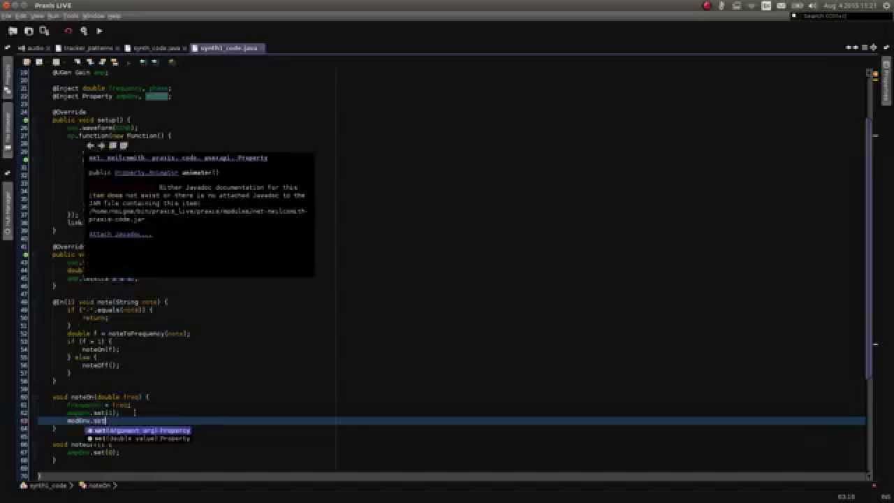
Just posted this Praxis LIVE video elsewhere, but some simple phase modulation (I think :wink: ) from about 6:00 …