[GLSL] Using Normal Maps to Illuminate a 2D Texture (LibGDX)

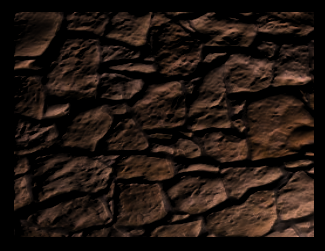
Result:

An image doesn’t really do it justice, so try out the LibGDX demo here:
http://www.mediafire.com/?ak4a5oso4cctmw8 (5.4 MB fat jar – simply double-click)

The illumination model seems to be a very complicated thing at first glance, but it’s actually really relatively simple mathematics. For more reading, see here.

The entire source of the LibGDX demo can be found here (excuse the messy code). The images used:
rock.png
rock_n.png
teapot.png
teapot_n.png

The application is very basic: it renders a quad with two active texture states, which are sampler2D uniforms in the fragment shader. The parameters are all uniforms for simple debugging purposes; although for performance you may not want to do this in practice.

The basic equation:

N = normalize(NormalColor.rgb * 2.0 - 1.0)
L = normalize(LightDir.xyz)

Diffuse = LightColor * max(dot(N, L), 0.0)

Ambient = AmbientColor * AmbientIntensity

Attenuation = 1.0 / (ConstantAtt + (LinearAtt * Distance) + (QuadraticAtt * Distance * Distance)) 

Intensity = Ambient + Diffuse * Attenuation

FinalColor = DiffuseColor.rgb * Intensity.rgb

The GLSL fragment shader. Could probably be cleaned up a little, and the booleans/yInvert are of course only there for test purposes.

#ifdef GL_ES
precision mediump float;
#endif
 
varying vec4 v_color;
varying vec2 v_texCoords;
uniform sampler2D u_texture;
uniform sampler2D u_normals;
uniform vec3 light;
uniform vec3 ambientColor;
uniform float ambientIntensity;
uniform vec2 resolution;
uniform vec3 lightColor;
uniform bool useNormals;
uniform bool useShadow;
uniform vec3 attenuation;
uniform float strength;
uniform bool yInvert;
 
void main() {
        //sample color & normals from our textures
        vec4 color = texture2D(u_texture, v_texCoords.st);
        vec3 nColor = texture2D(u_normals, v_texCoords.st).rgb;
 
        //some bump map programs will need the Y value flipped..
        nColor.g = yInvert ? 1.0 - nColor.g : nColor.g;
 
        //this is for debugging purposes, allowing us to lower the intensity of our bump map
        vec3 nBase = vec3(0.5, 0.5, 1.0);
        nColor = mix(nBase, nColor, strength);
 
        //normals need to be converted to [-1.0, 1.0] range and normalized
        vec3 normal = normalize(nColor * 2.0 - 1.0);
 
        //here we do a simple distance calculation
        vec3 deltaPos = vec3( (light.xy - gl_FragCoord.xy) / resolution.xy, light.z );
 
        vec3 lightDir = normalize(deltaPos);
        float lambert = useNormals ? clamp(dot(normal, lightDir), 0.0, 1.0) : 1.0;
       
        //now let's get a nice little falloff
        float d = sqrt(dot(deltaPos, deltaPos));       
        float att = useShadow ? 1.0 / ( attenuation.x + (attenuation.y*d) + (attenuation.z*d*d) ) : 1.0;
       
        vec3 result = (ambientColor * ambientIntensity) + (lightColor.rgb * lambert) * att;
        result *= color.rgb;
       
        gl_FragColor = v_color * vec4(result, color.a);
}

At a later point I may go into more details as to how this all works (targeting newbies) and how it could be implemented in a practical way. :slight_smile:

EDIT: Updated based on advice from theagentd and MatthiasM.

Without knowing a single thing about shaders… it’s very pretty ;D

To my knowledge you’re not supposed to normalize the light position? I mean, it only makes sense to normalize a vector, which it isn’t?

Technically it is a vector – “direction to the light source.” I’ve renamed it LightDir for clarity.

Ah, then it makes perfect sense. =S Did I mention it looks really nice?

Hmm, when I tested it I thought the effect was a little… subtle? Would it be possible to make it look more bumpy?

[quote]Hmm, when I tested it I thought the effect was a little… subtle? Would it be possible to make it look more bumpy?
[/quote]
Yes, you can set the intensity to a higher value when generating the normal map. You could also lower the lightDir.z for different results – the higher the value, the more subtle the effect may appear.

A programmatic way of doing the former might look like this in a shader:

//use a high intensity normal map
vec3 nColor = texture2D(u_normals, v_texCoords.st).rgb;

//i.e. zero intensity
vec3 nBase = vec3(0.5, 0.5, 1.0);

//mix the two based on a given amount between 0.0 and 1.0
//1.0 -> full strength, 0.0 -> no effect
nColor = mix(nBase, nColor, strength);

There might be some other way of doing it that I’m overlooking. For truer “bumpiness” you may need to use displacement or parallax maps. I haven’t looked into those yet, but I hope to soon. :slight_smile:

Ohhh, I’ve seen this in the Skyrim files, didn’t know what it was until now

This is very nice looking. I saw a similar technique on r/gamedev a week ago or so. I cinsider using it in a game i’m working on. Did you benchmark it on Android?

I have no mobile devices to test on. :frowning:

And yes it was inspired by a post I saw on /r/gamedev. In terms of performance it should be good; it simply requires one extra texture sample, a little math, and one or two uniforms. The downside is that your sprites need a normal map, so your texture memory will be doubled. Some other ideas for performance:

[]Use constants instead of uniforms where possible
[
]Use nearest neighbour filtering for textures
[]If you never use the vertex color, use a custom mesh that only sends {x, y, u, v} to the shader
[
]You could try packing the color and normals into the same texture atlas, but then you would need to send an extra (u, v) texcoord to the shader. Alternatively, you could use half-width texture atlases (e.g. 512x1024) and during initialization pack the color and normals into the same atlas (e.g. 1024x1024); then the normal texcoords would be (u + 0.5, v).
[]If you really want to save space, you could use a similar technique, but with pure bump instead of normals (i.e. black and white height map). This is closer to the post in /r/gamedev; and you could save the bump as a grayscale PNG and upload it as GL_LUMINANCE. Furthermore, if your color sprites don’t need alpha values for some reason, or you have other means of creating alpha, you could store the bump in the sprite sheet’s alpha component.
[
]You could also programatically generate normal/bump maps if you were really, really keen to trim down your app size.

I see this coming ;D

-Q6ISVaM5Ww

vtYvNEmmHXE

@matheus23

Wow… Not much more to say…

Yes. I was pretty impressed too, but It’s a pity, this is only for XNA, and the author somehow dropped development :frowning:

He actually has a write-up on the technical details of his engine here. In the end he suggests that a actual 3D engine might be better for performance.

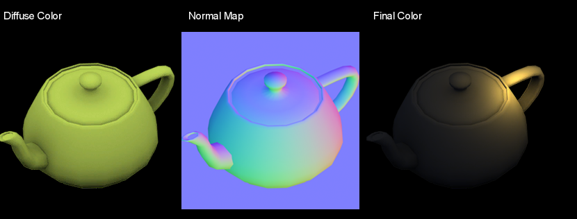
Regarding his technique, though, my code is already most of the way there. :slight_smile: For example, here’s what it looks like using his teapot color + normal maps.

Try the new demo here. You can also change the light depth (Z) and normal map strength.

There’s definitely something weird going on there… Try to set the z-value to 0. Also, no matter where I moved the light, I could not get the leftmost side of the teacup’s nozzle (uh, the part where the water comes out from… xD) to become bright.

I think your light direction calculation is really weird. I’d do it like this:


uniform vec3 lightPos; //3D position, x and y are the pixel coordinates on screen of the light, z is some psuedo-depth value

void main(){
    vec3 deltaPos = lightPosition - vec3(gl_FragCoord.xy, 0); //or was it fragPos - lightPos? =S

    vec3 lightDirection = normalize(deltaPos); //--> dot this with normal map
    float distanceSquared = dot(deltaPos, deltaPos); //Use for attenuation

    ...
}

spout :slight_smile:

Reminds me of my English teacher in high school. The best way to prove that someone isn’t as good at English as they think is to drag them out in the kitchen, open a drawer and tell them to start talking about those things. That’s the kind of stuff you learn from experience, not in school…

But anyway, I thought it was an automatic teapot with a built-in electric pump like we have here in Sweden, in which the spout actually works as a nozzle. Ah, fuck it. Just found out from Wiktionary that the word spout actually comes from Swedish… -_-’

I think you’re right that something is off with my light direction. Unfortunately your code does not seem to fix the issue; only makes it all look a little more wonky. Will have to look into it tomorrow…

[s]Like I wrote in the comment, you might have to switch the light position and the pixel position around:

vec3 deltaPos = lightPosition - vec3(gl_FragCoord.xy, 0);
to
vec3 deltaPos = vec3(gl_FragCoord.xy, 0) - lightPosition;

I don’t remember which one’s right… ._.[/s]

EDIT:

Found some code for 3D lighting…


    vec3 dPos = lightPosition - eyeSpacePosition;
    
    float diffuse = max(dot(normal, normalize(dPos)), 0.0);
    
    float falloff = 2000 / dot(dPos, dPos);
    
    fragColor = vec4(color * diffuse * falloff);

Note that in my case lightPosition is in eye space. Since my above code assumes that lightPos is the pixel position on screen, you’ll have to transform the light position properly on the CPU and upload the transformed position to the lightPos.

Damn, I know how hard it is to get lighting correctly. It’s really hard to see when it’s right. =S

Both result in strange lighting…

The following is giving me better results, though:

vec3 deltaPos = vec3(light - vec3(gl_FragCoord.xy, 0.0)) / vec3(resolution.xy, 1.0);

The rock texture looks way better now, thanks. :slight_smile: Will look into it a bit more later.

EDIT: Just saw your edit. Looks like the above fix is just a hack, which is probably why the teapot still looks a little off.

Ok, after a bit more reading, the issue is:
The normal is in tangent space, and the lightPos is not. So eye space wouldn’t work, either.

However, if I understand this correctly, my revised code (dividing by resolution) works because the clip space here is the same as tangent space. (Assuming my sprite isn’t rotated.)

For some normal maps like the teapot, the lighting only works correctly if I flip the Y value:

deltaPos.y = -deltaPos.y;

See the result, which seems more accurate: (attenuation disabled)

The above Y flip does not work with the rock texture, though. See here; the light source is in the bottom right but it appears to be hitting the top left of the rock edges.

Without the Y flip it appears correctly:

Almost there. Not sure why some require this Y flip and others don’t… My brain is fried now…

EDIT: Some programs seem to invert the green channel… A better solution may be to invert the green channel of the normal map before doing any calculations. I will fix this up and upload the new version.