GL_POINT Voxels shifting when moving camera

This thread was created to migrate over the replies from the thread “What I did today”

@KaiHH I don’t mean to subvert the topic of this thread, but I’m also using java (Jmonkey) and happened to come across this this particular post. My question is regarding the GL_POINT method as outlined in the paper “A Ray-Box Intersection Algorithm and Efficient Dynamic Voxel Rendering”. I seem to be running in an issue with GL_POINTs that are at a distance, say >30 world units away. The issue is that when moving or rotating the camera the ray-traced voxel seems to shift near the edges of the GL_POINT billboard.
Attached are the use case that shows the issue I’m encountering:

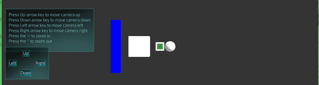
The center green cube is ray traced and I have added a white background to better visualize the issues.

Here is the result when I rotate the camera downward:

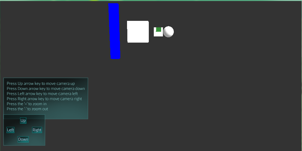
The green cube seems to have shifted near the top edge of the point billboard.
It seems as if this issue only seems to occur when voxels are far away.

Here is the way I’m currently generating the ray in my fragment shader:


vec3 getRayDir(vec3 camPos, vec3 viewDir, vec2 pixelPos) {
     vec3 camRight = normalize(cross(viewDir,vec3(0.0, 1.0, 0.0)));
     vec3 camUp = normalize(cross(viewDir,camRight));
     return normalize(pixelPos.x*(camRight) + pixelPos.y*camUp + CAM_FOV_FACTOR*viewDir);
 }
void main(){
    //camPos and camTarget are passed in through material parameters
    //camTarget is the forward vector of the camera, the formula I use to get the forward is: camPos + (normalize(g_CameraDirection)*1.0);

    
    vec2 p = (-resolution.xy + 2.0*gl_FragCoord.xy) / resolution.y;
    
    //ray origin
    vec3 ro = camPos;
   //ray direction
    vec3 rd = getRayDir(camPos,normalize(camTarget - camPos), p);
}

The use of linear combinations to compute the ray direction with a computed forward, up and right vectors and also a CAM_FOV_FACTOR seems a bit shady. I’ve looked into JMonkey’s https://javadoc.jmonkeyengine.org/com/jme3/shader/UniformBinding.html and seeing that it gives you all the uniforms you need, I’ve JMonkey-ified my current ray generation code (just replaced my own uniforms with JMonkey’s):
This is all you need to generate a correct ro and rd:


vec2 p = 2.0 * vec2(gl_FragCoord.xy) / (g_ViewPort.zw - g_ViewPort.xy) - vec2(1.0);
vec3 ro = g_CameraPosition;
vec4 rdh = g_ViewProjectionMatrixInverse * vec4(p, -1.0, 1.0);
vec3 rd = rdh.xyz/rdh.w - ro;
/* Optionally normalize rd (but not necessary for algorithm) */
//rd = normalize(rd);

It does contain one matrix * vector multiplication, which you can factor out into host code, but the above works and you can use it to check whether the error was in your ray generation code or is somewhere else.

Thanks so much for helping me out so far. If Im understanding the method provided, the FragCoord is converted from window space to NDC space, then to get to homogeneous clip space multiply by the inverse of the ViewProjectionMatrix, and finally to get the eye ray direction we would divide by the W component of rdh vector.

Yes, and it’s just what you also did in your code (except that yours will have a scale in the x axis for aspect ratios != 1).

Almost. The ‘p’ is assumed to be in NDC space, yes. Now, since the uninverted (projection * view) matrix transforms from “world” space to homogeneous clip space, we want the opposite and therefore transform NDC (which is just synonymous to homogeneous clip space with w=1) into “homogeneous world space” and then to actual 3D world space by perspective division. This essentially gives the world-space 3D coordinates of the point on the near clipping plane for the current/respective fragment/pixel. Then we convert that position into a direction by subtracting the world-space camera position from it.