So I have been working on a rather simple program that just renders a shape. However, as it’s rendering, it has some miscalculated pixels around where the polygons meet. From my experience with ray tracing, I know these things are usually caused by a precision error. Does anyone know a workaround to this?
(I have turned off AA in order to emphasize the effect for demonstration purposes.)
Make sure all triangle vertices and edges line up. The vertices have to be bitwise identical. As for edges: adjacent triangles have to share edges (meaning: the two vertices that the two triangles have in common, must be bitwise identical).
A setup like this will cause rendering artifacts: (I’m using quads for simplicity)
 ________
|___|    |
|___|____|
because the bigger quad does NOT share all edges with its neighbours: it has independent edges that merely overlap. After several matrix transformations the center of the two short edges and the center of the long edge have slightly deviated, causing the rendering artifacts.
Thanks for the help. I have checked through the code and I can confirm there aren’t any setups like the one in your diagram. However, I’m still not sure how to make sure vertices are bitwise identical. Is there a certain way you are supposed to put vertices into buffers?
Yes just putting ints into a floatbuffer is going to cause slight rounding errors. However just changing them to floats and dumping them in there won’t help either.
What you need to do is generate positions and then reuse those positions for each vertex.
The best way to think of this is a cube. A cube has only 8 positions(the corners), but it has 24 vertices! Why is this? Well you have a square with 4 vertices that makes up one side of the cube, to make up the full cube you’ll have 6 sides, hence the 24 vertices. (Vertices include other information such as normals, texture coordinates, color, etc.)
Now if you generate positions for all 24 vertices they will all be slightly different and you’ll get the artifacts that you see in your program.
You mentioned this is a raytracer, precision errors can be mitigated by using some epsilon value. In GL fragment shaders I usually use an epsilon of 0.0005, but adjust up and down as needed to make it as tight as possible.
This epsilon is used when comparing the values you generate to calculate the intersection of the ray with the object. Instead of comparisons against zero, you use the epsilon.
I suspect your shape is made out of 4 cubes. What you’re seeing is a depth precision issue where you can see the internal edges due to z-fighting. Try either removing the internal faces or improve the depth precision by reducing the far-plane/near-plane ratio.
False. To actually reuse the vertices (as in they don’t get reprocessed for each triangle they partake in) you need to use glDrawElements() with an index buffer. Most likely you won’t actually need that though unless you have a huge number of vertices (100 000+).
Huh? If I store the positional data in a custom vector3 class then pass the x, y, z values to openGL using glVertex3f() multiple times the positions should be in the exact same place.
Now I will admit that I don’t know what’s going on under the hood, but I’ve never ran into any seams/artifacts using immediate mode that way.
You’re right. Two different vertices that happen to have the exact same attributes will look the same on the screen, but they still aren’t the same vertex and therefore will be recomputed. The GPU has something called the vertex cache that allows it to reuse vertices when using certain special primitive types and when doing indexed rendering. The point of this is to reduce memory usage (when storing the vertex data on the GPU) and improve performance as fewer vertices has to be processed.
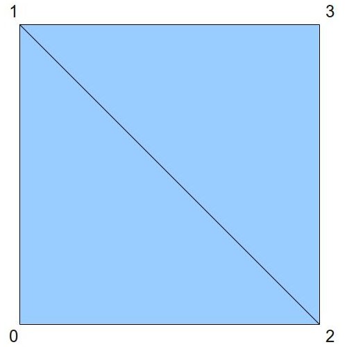
When it comes to primitive types, the simplest example is GL_QUADS. The only thing a graphics card can draw is points, lines and triangles, so a quad is drawn as 2 triangles forming a quad, like this:
If you draw a quad using GL_TRIANGLES by manually drawing 2 triangles, you’ll be submitting 3+3=6 vertices, with vertex 1 and 2 both being duplicated. In essence, 33% of the vertex processing is wasted. If you instead use GL_QUADS, you can simply submit 4 vertices and have the GPU form 2 triangles from them for you. In this simple case, it’s enough to know that the GPU does NOT reprocess vertex 1 and 2 for the second triangle. Instead, it reuses them. There are other more advanced primitive types that allow for even better reuse, like GL_LINE_STRIP/LOOP, GL_TRIANGLE_STRIP/FAN and GL_QUAD_STRIP. Before indexed rendering, many 3D modelling programs had functions to “stripify” 3D models, e.g. convert them into a number of triangles strips to massively cut down on vertices. A triangle strip reduces the number of vertices processed by up to 66.6%.
Nowadays, those fancy primitive types aren’t as relevant anymore as we indexed rendering. Indexed rendering allow us to submit first a list of vertices, and then a list of indices to this vertex list for the corners of our lines/triangles. The above quad could be drawn using GL_TRIANGLES by uploading the 4 corner vertices to the GPU and then creating an index buffer which contains the values {0, 1, 2}, {2, 1, 3}. In this case, it gets a bit more complicated, but in essence the GPU uses a fixed size vertex cache to avoid reprocessing vertex 1 and 2, but it may not always be able to do that. The vertex cache is usually only 16 or 32 vertices large (depending on the hardware), so it does not guarantee that each vertex will only be processed once, but in your average continuous 3D model it does a really good job at cutting down the vertex load.
[quote]As for making all the vertices reused, would I have to use a glDrawElements approach for this?
[/quote]
It seems that I read this line wrong. (thought we were still talking about positions)
You’re right to reuse vertices you would have to use glDrawElements, my bad.